

 français


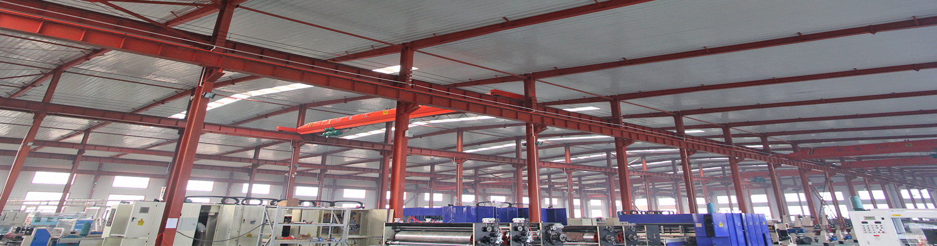

Steel Structure Warehouse Load Designing for Strength
Designing a steel structure warehouse for strength is a fundamental engineering task that balances safety, economy, and functionality. Here’s a structured breakdown of the process, key considerations, and load types.
1. Core Philosophy: The Load Path
The fundamental goal is to define a clear, continuous path for all loads (gravity, wind, snow, etc.) to travel from their point of origin down to the ground. Every component must be designed to transmit these loads safely.
Path: Roof Cladding → Purlins → Rafters/Trusses → Columns → Side Girts → Foundation → Ground.
2. Key Load Types to Consider (Loading Codes: ASCE 7, Eurocode, etc.)
Loads are combined in various ways (e.g., 1.2D + 1.6L + 0.5S) to find the worst-case scenario.
A. Primary Loads (Strength Design)
①.Dead Loads (D): Permanent, static loads.
Weight of the steel frame itself.
Weight of roof and wall cladding (metal sheets, insulation).
Permanent services (sprinkler lines, permanent lighting, HVAC units).
·Design Implication: Largest influence on columns and foundations.
②.Live Loads (L): Variable, movable loads not from environmental forces.
·Roof Live Load: Maintenance personnel, equipment. Typically 0.96 kN/m² (20 psf) in many codes, often reducible for large areas.
·Floor Live Load (if mezzanine): Storage, forklifts, pallets. This is critical. A warehouse floor might be designed for 10-25 kN/m² (200-500 psf) or more, depending on stacking height and equipment. Forklifts impose concentrated wheel loads.
③.Environmental Loads:
·Snow Load (S): Governed by geographic location, roof slope, and thermal factors. Crucial for roof members. Must consider unbalanced snow loads, drifts at parapets, and sliding snow.
·Wind Load (W): Often governs the design of side walls, bracing, and connection design. Calculated using:
Basic wind speed (risk category).
Building height and exposure category (open terrain, suburban).
Internal pressure coefficients (doors open/closed).
External pressure coefficients (suction on walls/roof).
·Seismic/Earthquake Load (E): Required in active zones. Depends on soil type, building mass, and ductility of the frame. Influences connection design and bracing heavily.
B. Secondary but Critical Loads
·Crane Loads (if applicable): Massive impact. Consider:
Vertical load from lifted weight + hoist weight.
Lateral longitudinal and transverse loads from crane movement/braking.
Impact factors (typically 25% of lifted load).
·Collateral Loads: From non-structural elements like utilities.
·Special Loads: Impact from forklifts, equipment vibrations, etc.
3. Step-by-Step Design Process for Strength
①.Architectural & Functional Layout:
·Define clear spans, bay spacing (e.g., 8m x 6m), eave height, and roof slope.
·Locate doors, openings, and mezzanines. Crane runways if needed.
②.Preliminary Sizing & Framing Selection:
·Primary Frame: Rigid frames (moment-connected), or simple frames with trusses and bracing.
·Secondary Members: Choose purlin/girt sections (C, Z, or built-up). Spacing (~1.2m-1.8m) affects cladding and primary member design.
·Bracing System: Essential for stability. Diagonal rods or angles in roof and walls (in vertical planes) to resist wind/seismic loads. Consider longitudinal bracing along the ridge.
③.Load Calculation & Combination:
·Calculate all loads from codes.
·Apply load combinations (Strength Design: LRFD, or Allowable Stress Design: ASD) to find the most critical demand on each member.
④.Analysis & Member Design:
·Analysis: Use structural analysis software (STAAD.Pro, SAP2000, RISA, Tekla) or manual methods for simple structures.
·Member Design:
Rafters/Purlins: Check for bending stress (major and minor axis), shear, and deflection (serviceability). Purlins are often continuous over multiple supports.
Columns: Check for axial compression and bending (from wind or eccentric loads). The unbraced length (weak axis vs. strong axis) is critical. Use the effective length factor (K) in the column formula.
Trusses: Design top/bottom chords for axial force + bending, webs for axial forces. Check buckling capacities.
Connections: THE MOST IMPORTANT PART. Bolted (bearing-type or slip-critical) or welded. Design for shear, tension, and moment transfer. Eccentricities must be accounted for. Base plates must resist uplift (wind) and bearing (gravity).
⑤.Deflection & Serviceability Checks:
·Strength ensures safety; deflection ensures functionality.
·Roof Deflection: Typically limited to Span/240 for live load.
·Vertical Deflection (Crane Girders): Very strict, e.g., Span/800.
·Lateral Sway: Limited to Height/400 to prevent cracking of cladding.
⑥.Detailing & Drawings:
·Clear fabrication and erection drawings.
·Specify materials (A992 Gr. 50 steel common), bolt grades (A325, A490), weld types.
·Corrosion protection (galvanizing, painting).
4. Common Pitfalls to Avoid
①.Ignoring Load Path Continuity: A strong beam is useless if its connection is weak.
②.Underestimating Wind Uplift: This can rip roofs off. Ensure roof-to-purlin and purlin-to-rafter connections are designed for tension.
③.Neglecting Stability: Failing to design adequate bracing for columns and beams during construction and in-service. Consider P-Delta effects for slender frames.
④.Forgetting Construction Loads: Erection loads can govern. Specify proper bracing sequences.
⑤.Incorrect Load Combinations: Not using the most critical combination for the member being checked.
⑥.Poor Drainage Design: Ponding water is a common cause of roof collapse. Ensure adequate slope and camber.
Catégories
dernier blog
Mots clés


Pour Demandes de renseignements sur nos produits ou Pricelist, laissez-nous s'il vous plaît et nous serons en contact dans les 24 heures.
© droits dauteur: 2026 Hebei Baofeng Steel Structure CO.,LTD Tous les droits sont réservés.

IPv6 réseau pris en charge


 +8615720226351